Wednesday, March 5, 2014

RIP Split-Horizon , RIP Timers


Lessons Learned:


RIP Auto-summary

RIPV1 – is default when configuring RIP

RIPv2 is classless but does automatic classful summarization by default.

-Disabled with no auto-summary


VLSM is supported within the same major network.

Advertisements between major network boundaries are summarized to classful boundary

-Can result in traffic black holes.


Split Horizon –

If enabled will stop routes from being sent back out the interfaces they we’re learned on.

RIP is a distance vector protocol.

Updates received in an interface will not be sent back out the same interface.

Basically if you advertise a route to me, I don’t want to send the same route back to you. This could result in a loop in the data-plane.

-Undesirable on partial mesh NBMA networks.

Enabled by default on all interfaces except main interface in Frame Relay. It will be enables on all other interfaces.

Ex: in multipoint it would be enabled on the sub interfaces.        

-no ip split-horizon to disable,

Verifcation

#sh ip interface

This is show if Split horizon is enabled on the interface.

Note: remember once a RIP route has been down for over 240 seconds they will be removed from the routing table.

We can also use the debug IP RIP to see what routes are being advertised. And what is being received.


R1#sh ip interface fa0/0

FastEthernet0/0 is up, line protocol is up

  Internet address is 192.168.12.1/24

  Broadcast address is 255.255.255.255

  Address determined by non-volatile memory

  MTU is 1500 bytes

  Helper address is not set

  Directed broadcast forwarding is disabled

  Multicast reserved groups joined: 224.0.0.9

  Outgoing access list is not set

  Inbound  access list is not set

  Proxy ARP is enabled

  Local Proxy ARP is disabled

  Security level is default

  Split horizon is enabled – Split Horizon is enabled.

  ICMP redirects are always sent

  ICMP unreachables are always sent

  ICMP mask replies are never sent

  IP fast switching is enabled

  IP fast switching on the same interface is disabled

  IP Flow switching is disabled

  IP CEF switching is enabled

  IP CEF Fast switching turbo vector

  IP multicast fast switching is enabled


Debug IP RIP :

*Mar  1 00:04:42.303: RIP: sending v2 update to 224.0.0.9 via FastEthernet0/0 (192.168.12.1)

*Mar  1 00:04:42.307: RIP: build update entries

*Mar  1 00:04:42.307:   10.1.1.0/24 via 0.0.0.0, metric 1, tag 0

*Mar  1 00:04:43.075: RIP: sending v2 update to 224.0.0.9 via Loopback1 (10.1.1.1)

*Mar  1 00:04:43.079: RIP: build update entries

*Mar  1 00:04:43.079:   192.168.12.0/24 via 0.0.0.0, metric 1, tag 0

*Mar  1 00:04:43.091: RIP: ignored v2 packet from 10.1.1.1 (sourced from one of our addresses) – shows split horizon at work – the update is not process and the route is ignored

 
Debug IP routing – will show any and all maintenance on the routing itself.


RIP Convergence Timers:

Global – will affect all interfaces

-Timers basic (update) (invalid) (Holddown) (flush)


Interface level – will affect just the interface.

-#ip rip advertisement (interval)


Note: All the timers start counting at the same time index. The default is 30 seconds.

Once a router receives an update in , the rest of it’s timers which are the invalid, hold down, and flush timers. These all start counting up.


Basically from the last time the router received an update, if the time gets to 180 seconds, the route becomes “invalid” and it goes into “hold down”.  Most of the time the invalid and hold down have the same value. Technically  they have two different purposes.

The hold down says – when I receive a new update in regarding a prefix, only accept it if it has the same or better metric. To verify the routing information is not looping around the network while its aging out.


The Invalid says – the route is possibly down in the routing table.

Flush timer is 240 sec by default, if it does past that time –remove the route.


Verify the timers:


# sh ip protocols

R3#sh ip protocols

Routing Protocol is "rip"

  Outgoing update filter list for all interfaces is not set

  Incoming update filter list for all interfaces is not set

  Sending updates every 30 seconds, next due in 16 seconds – send updates

  Invalid after 180 seconds, hold down 180, flushed after 240 – invalid, hold, and flush

  Redistributing: rip

  Default version control: send version 2, receive version 2

    Interface             Send  Recv  Triggered RIP  Key-chain

    FastEthernet0/0       2     2                                   

    Loopback1             2     2                                   

    Loopback33            2     2                                   

  Automatic network summarization is not in effect

  Maximum path: 4

  Routing for Networks:

    1.0.0.0

    10.0.0.0

    192.168.23.0

  Routing Information Sources:

    Gateway         Distance      Last Update

    192.168.23.2         120      00:00:22

  Distance: (default is 120)

The time timer values apply to either RIP version  1 or 2.

To lower the values.

R3(config-router)#timers basic 5 20 20 30

This says – change the updates to 5 seconds / invalid to 20 seconds / Hold to 20 seconds and flush to 30 seconds.

Note: if you set the hold down to 0, the route will never go into hold down.

Verification:

R3#sh ip protocols

Routing Protocol is "rip"

  Outgoing update filter list for all interfaces is not set

  Incoming update filter list for all interfaces is not set

  Sending updates every 5 seconds, next due in 3 seconds

  Invalid after 20 seconds, hold down 20, flushed after 30

Note: the timers in RIP are not 100% accurate, the RIP process uses something known as RIP Jitter. Which is basically a randomization of the timers to make sure the router is not sending or receiving updates out the interface at the exact same time index. This is why the timers are large by default.                                        

There is a limit to the packet format to RIP. So some updated do not make it in each update.
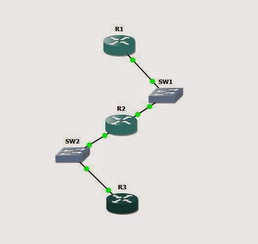
Tuesday, March 4, 2014

RIP Overview, Versions, Auto-Summary

Lessons Learned:
RIP v2 – Version one is now considered legacy and is a Class-full protocol.
Not a very feature rich protocol. RIP is the most basic of all dynamic routing protocols.

Distance Vector IGP
-uses split-horizon, poison reverse, and count to infinity (loop prevention)
-UDP port 520 for transport

Two version
RIPv1
-classful
Updates as broadcast

RIPv2
-Classless
-updates as multicast to 224.0.0.9

RIP – only knows about its directly connected neighbors and what the neighbors advertise. RIP does now know about the overall topology.
RIP’s distance vector behavior is often called “routing by rumor” because when the router receives an update in, it has no visibility about where the update came from. It has no idea about the overall topology.

RIP – Uses UDP port 520 for reachability. If there’s a firewall between neighbor routers or access-lists, we need to make sure UDP 520 is not filtered.
RIPv2 – is a classless protocol, this means it support the advertisements of subnets or supersets that are of any VLSM.
RIPv1 – packet does not include a field of the route for the VLSM address. This means every subnet had to be identical.
EX all / 24’s or all /26’s – as long as the masks are the same because the subnet mask is not advertised in the updates.
RIPv1 also uses broadcasts for its updates. This means each device has to process all updates.
RIPv2 – uses a multicast address routing control plane exchange for its updates.
RIPv2 is classless and so it can support LSM – it has two fields – one for the address and the subnet.

Configuring and enabling RIP.
Easy process –

-enable the global process:
-router rip

Enable the interface process
-network (address)  - No process number no AS number, etc….
-matches major network only

Verification
-sh ip protocols
-sh ip rip database
-dubug ip rip.


LAB:

R3#
router rip
network 10.0.0.0
network 192.168.23.0
no auto-summary

debug output from initial sync between two peers over network 192.168.23.0 / 24. Each router R3 and R2 have loopbacks addressed in the 10.1.x.x /24 space. This is the output from a RIP version 1 initial Sync.

Initial peer update from RIP V1

*Mar  1 00:16:20.347: RIP: sending request on FastEthernet0/1 to 255.255.255.255
*Mar  1 00:16:22.343: RIP: sending v1 flash update to 255.255.255.255 via FastEthernet0/1 (192.168.23.2)
*Mar  1 00:16:22.343: RIP: build flash update entries - suppressing null update
*Mar  1 00:16:27.319: RIP: received v1 update from 192.168.23.3 on FastEthernet0/1
*Mar  1 00:16:27.319:      10.0.0.0 in 1 hops
*Mar  1 00:16:46.371: RIP: sending v1 update to 255.255.255.255 via FastEthernet0/1 (192.168.23.2)
*Mar  1 00:16:46.371: RIP: build update entries - suppressing null update
*Mar  1 00:16:52.859: RIP: received v1 update from 192.168.23.3 on FastEthernet0/1
*Mar  1 00:16:52.859:      10.0.0.0 in 1 hops – ( I have

Initial peer update from RIP v2
*Mar  1 00:25:40.299: RIP: build flash update entries
*Mar  1 00:25:40.299:   10.1.2.0/24 via 0.0.0.0, metric 1, tag 0
*Mar  1 00:25:40.299: RIP: sending v2 flash update to 224.0.0.9 via Loopback1 (10.1.2.1)
*Mar  1 00:25:40.299: RIP: build flash update entries - suppressing null update

Update after adjacency:

*Mar  1 01:32:58.371: RIP: received v2 update from 192.168.23.3 on FastEthernet0/1
*Mar  1 01:32:58.371:      10.1.3.0/24 via 0.0.0.0 in 1 hops
*Mar  1 01:33:22.067: RIP: sending v2 update to 224.0.0.9 via Loopback1 (10.1.2.1)
*Mar  1 01:33:22.071: RIP: build update entries                                                                                                            
*Mar  1 01:33:22.071:   10.1.3.0/24 via 0.0.0.0, metric 2, tag 0
*Mar  1 01:33:22.075:   192.168.23.0/24 via 0.0.0.0, metric 1, tag 0
*Mar  1 01:33:22.083: RIP: ignored v2 packet from 10.1.2.1 (sourced from one of our addresses)

Note: from the global routing table when configuring RIP there can only be one rip process.

The network statement tell the RIP process what interfaces do we want to send updates out of and what interface do we want to listen for updates on.
The network statement supports only classful networks. This however doesn't control what is advertised, it simply controls what interface the routing process is enabled on.

Note: Since the network statement only matches the classful network if we want to run RIP on only one interface and we have other interfaces in the same classful network we can have issues. We would have to filter updates coming in via access-lists or configure the interfaces as passive. Etc.

Once the protocol is enabled, we can verify with the following commands.

#Sh ip protocols – shows the timers, interfaces, updates, protocol version and classful networks that RIP is routing for.

R2#sh ip protocols
Routing Protocol is "rip" – running RIIP
  Outgoing update filter list for all interfaces is not set
  Incoming update filter list for all interfaces is not set
  Sending updates every 30 seconds, next due in 24 seconds
  Invalid after 180 seconds, hold down 180, flushed after 240
  Redistributing: rip
  Default version control: send version 2, receive version 2
    Interface             Send  Recv  Triggered RIP  Key-chain
    FastEthernet0/1       2     2                                   
    Loopback1             2     2                                   
  Automatic network summarization is not in effect
  Maximum path: 4
  Routing for Networks:
    10.0.0.0
    192.168.23.0
  Routing Information Sources:
    Gateway         Distance      Last Update
    192.168.23.3         120      00:00:03
  Distance: (default is 120)

Once RIP receives and update in an interface – they go into the RIP database for processing before they go into the routing table.
RIP – in RIP there’s two different data structures. One that has all the routes that we’re advertising and receiving, this goes into the RIP database. Then the active routes that we are actually using that go into the routing table or FIB table.

Sh ip rip database:

R3#sh ip rip database
10.0.0.0/8    auto-summary
10.1.2.0/24
    [1] via 192.168.23.2, 00:00:10, FastEthernet0/0
10.1.3.0/24    directly connected, Loopback1
192.168.23.0/24    auto-summary
192.168.23.0/24    directly connected, FastEthernet0/0

Dubug ip rip

R3#
*Mar  1 03:05:13.179: RIP: sending v2 update to 224.0.0.9 via Loopback1 (10.1.3.1)
*Mar  1 03:05:13.183: RIP: build update entries
*Mar  1 03:05:13.183:   10.1.2.0/24 via 0.0.0.0, metric 2, tag 0
*Mar  1 03:05:13.187:   192.168.23.0/24 via 0.0.0.0, metric 1, tag 0
*Mar  1 03:05:13.195: RIP: ignored v2 packet from 10.1.3.1 (sourced from one of our addresses)

Note: will so any updates advertised and received – also any authentication errors, etc.

RIP Versions:

Default processing
-send version 1 updates
-listen for versions 1 & 2 updates

Modifying the version
-version (process level)
-ip rip receive version  - interface level
-ip rip send version       - interface level

Verification:
-sh ip protocols

Configuration –
No separation between version 1 & 2. IOS will send version 1 updates by default but listen bot v1 and v2.
We can change the default behavior under each interface in the process. Of globally with the rip then version, ect.

Global:
R3(config)#router rip
R3(config-router)#version 2

Interface level Commands:

R3(config-if)#ip rip send version ?
  1  RIP version 1
  2  RIP version 2
R3(config-if)#ip rip send version 2
R3(config-if)#ip rip rec          
R3(config-if)#ip rip receive v
R3(config-if)#ip rip receive version 2
R3(config-if)#

RIP Auto-Summary:
RIPv2 is classless but does automatic classful summarization be default.
-Disabled with the “no auto-summary” command under the process.

VLSM is supported within the same major network.
Example for the classful network
10.1.1.0 /24
10.1.2.0 /24
10.1.3.0 /30
All fall under the classful network of 10.0.0.0 / 8. Basically the class A, B,C networks, etc.

Classful binary review.
Each Octet is broken into 8 bits. The first 4 of those bits define the network class.
Example:
00000000 – the first 4 define the class
Oxxx = Class A netwok
10xx = Class B network
110X = Class C network
1110 = Class D network – reserved for Multicast
1111 = Class e network.

Advertisements between major network boundaries are summarized to classful boundary
-again this can result in traffic black holes.

Sh ip protocols
R3#sh ip protocols
Routing Protocol is "rip"  -- we are running RIP
  Outgoing update filter list for all interfaces is not set  -- No filter set (distribute list, prefix, etc)
  Incoming update filter list for all interfaces is not set -- No filter set
  Sending updates every 30 seconds, next due in 18 seconds  --
  Invalid after 180 seconds, hold down 180, flushed after 240 – after 240 second will be removed from DB and routing table
  Redistributing: rip
  Default version control: send version 2, receive version 2 – send and rec version are at 2 because I hard coded them
    Interface             Send  Recv  Triggered RIP  Key-chain
    FastEthernet0/0       2     2                                   
    Loopback1             2     2                                   
  Automatic network summarization is not in effect – we are using auto – summary.
  Maximum path: 4  -- we have 4 maximum equal cost paths. Same longest prefix, metric value, we will install up to 4 routes
  Routing for Networks: - what interfaces will have the protocol enabled on if they fall in the major network
    10.0.0.0
    192.168.23.0
  Routing Information Sources: -- these are the neighbors that we are learning RIP from with default AD of 120
    Gateway         Distance      Last Update
    192.168.23.2         120      00:00:00
  Distance: (default is 120)

Sh ip rip database.

R3#sh ip rip database
10.0.0.0/8    auto-summary   -- routing for major networks
10.1.2.0/24
    [1] via 192.168.23.2, 00:00:13, FastEthernet0/0
10.1.3.0/24    directly connected, Loopback1
192.168.23.0/24    auto-summary
192.168.23.0/24    directly connected, FastEthernet0/0
R3#

Note: with the default version 1 - if we receive updates that are VLSM – we will assume the subnet of the mask that the interface that I was received on. Example – if my interface has a /24 mask, it will assume all the subnets coming from me will have a /24 mask.

Note: Both versions of RIP support the advertisements of host routes.

Configured L0 33
interface Loopback33
 ip address 1.2.3.4 255.255.255.255
end

advertised it in RIP
R3(config)#router rip
R3(config-router)#network 1.2.3.4
router rip
 version 2
 network 1.0.0.0

even though auto-summarization is on –

the neighbor router still sees the host route
R2#sh ip route rip
     1.0.0.0/32 is subnetted, 1 subnets
R       1.2.3.4 [120/1] via 192.168.23.3, 00:00:28, FastEthernet0/1

Note: with RIP Version 2 and auto-summary on, the routers will receive multiple classful summaries about the same major network. When they cross boundaries they will be summarize to the major network.       


Monday, March 3, 2014

Backup Interface:


Lessons Learned:

Tracks line protocol of "primary" interface

-if line protocol is up, backup interface is in standby

-If lin protocol is down, backup interfce is active

Configuration.

-backip {interface | load | delay|}

-placed on the promary interface

What causes the line protocol to go down?

This concept is another variation of a primary and secondary interface like floating static routes.

Back up interface orginall y came form Dial-backup senarios, where theres a pimary frame or T1 up and the backup would be an anolog or dial-up. you'd only use dial interface if the primary was down or there was an unusual load on the link. The reason being is that the analog or dial links we're orginally pay per use.

Note: this willbe under dial technologies under Cisco's configuraitpon reference guides.

If the load option is configured or the dial link. You will need to specify the load interface under the interface. the load by default is checked in 5 minute intervals. If we want to change the sample rate, under the interface we need to specify the sample time.

EX:

# Interface s0/0/0

 #load-interval 60 (sets the sampling to 60 seconds.)

Backup interface config:

Under the primary interface - we need to tell it what's the backup interface:

EX:

#interface  serial 0/0

#backup interface serail 0/1

In this config there's normally only one interface in the up/up at one time. As long as the router has a path - route to destination off each link - it doesnt matter what the metric is.

My lab has 3 routers-

R1 and R2 are connected together vis FA/0

R3 has a serial link to both routers. It has two serail links to R1, which is being used as a border router. I've installed loopbacks on R1 for networks 1.1.1.0/24 and 2.2.2.0/24.

The primary serail link to R1 is on subnet: 13.0.0.0 /24

The backup serial link (s0/1) is on subnet 14.0.0.0/24

currently they both have reachability over each link to R1.

Now - i'll confiure the backup link on S0/0 to point to S0/1.

R3(config-if)#backup interface serial 0/1

*Mar  1 00:19:04.527: %LINK-5-CHANGED: Interface Serial0/1, changed state to standby mode
*Mar  1 00:19:05.527: %LINEPROTO-5-UPDOWN: Line protocol on Interface Serial0/1, changed state to down
R3#sh run interface ser
R3#sh run interface serial 0/0
Building configuration...


Current configuration : 110 bytes
!
interface Serial0/0
 backup interface Serial0/1
 ip address 13.0.0.3 255.255.255.0
 clock rate 2000000
end


R3#sh run | i ip route
ip route 0.0.0.0 0.0.0.0 Serial0/0 -
ip route 0.0.0.0 0.0.0.0 13.0.0.1 2


Serial0/1                  14.0.0.3        YES manual standby mode          down   
Serial0/2                  32.0.0.3        YES manual up                    up  


Note: that serial 0/1 is in the "standby Mode" - this means that that its line protocol is down.


The key point is that a route can only be installed in the orutiung table if the interface that is recurses to has it's line protocol up - up. If down - no routes can be installed.

R3#sh ip route static
S*   0.0.0.0/0 is directly connected, Serial0/0


The current route installed is over the other serial link.
This trace verifies the current route.

Type escape sequence to abort.
Tracing the route to 2.2.2.2


  1 13.0.0.1 36 msec *  40 msec
R3#


If the now prmary link goes down - the standy link will go active until the primary link retunrs to up.

Once i shut the interface on teh other side of the link for S0/0 - the backup link goes active:

R3#
*Mar  1 00:37:45.695: %LINK-3-UPDOWN: Interface Serial0/1, changed state to up
R3#
*Mar  1 00:37:46.699: %LINEPROTO-5-UPDOWN: Line protocol on Interface Serial0/1, changed state to up


R3#traceroute 2.2.2.2

Type escape sequence to abort.
Tracing the route to 2.2.2.2


  1 14.0.0.1 44 msec *  40 msec
R3#


Once I bring the primary backup:

*Mar  1 00:41:13.615: %LINEPROTO-5-UPDOWN: Line protocol on Interface Serial0/0, changed state to up
R3#
*Mar  1 00:41:15.631: %LINK-5-CHANGED: Interface Serial0/1, changed state to standby mode
*Mar  1 00:41:16.631: %LINEPROTO-5-UPDOWN: Line protocol on Interface Serial0/1, changed state to down


 Now we can see the orginal primary link is backup - and the backup link has gone to standby.

Serial0/0                  13.0.0.3        YES manual up                    up     
FastEthernet0/1            unassigned      YES unset  administratively down down   
Serial0/1                  14.0.0.3        YES manual standby mode          down   
Serial0/2                  32.0.0.3        YES manual up                    up  


Also that the route has be installed again in the routing table.

S*   0.0.0.0/0 is directly connected, Serial0/0


Sunday, March 2, 2014

Floating Static Routes

Lessons Learned:

-Static route with higher administrative distance used to backup another route.

-Routes must be if equal longest match.

 Static routes by default will always have an administrative distance One. Regardless is the route is pointing at a next-hop value or to the interface.

Note: the interface itself is a distance on Zero but the static route AD will always be one.

Example:

I have a static default route pointing to the upstream next-hop and also the interface.

R3#sh ip route static
12.0.0.0/24 is subnetted, 1 subnets
S 12.0.0.0 [1/0] via 30.0.0.2
S* 0.0.0.0/0 [1/0] via 12.0.0.2
is directly connected, FastEthernet0/0

Both the routes show up in the routing table with equal metrics.

If both entries show up in the routing table that implies there's an equal longest match between the two routes. In this case they both point the zero route and they both have an AD of "1".

For the Floating Static Route:

We can add the two default routes and then change the administrative distance of one of the routes to a higher metric.

Note: when we're looking at equal longest match between different protocols we are looking at the administrative distance. When looking at the equal longest match between the same protocol, then we are looking at the Metric.

So for static routes, if comparing static to say OSPF for example, then we're looking at the distance.

When comparing two static routes against each other, we're looking at the metric value. From a configuration perspective the Metric is the same as the distance.
EX:

ip route 0.0.0.0 0.0.0.0 12.0.0.2 3 - this basically installs a second default route but with an administrative / metric of "3". Which is larger than the connected and static AD.

Note: When we look to install a route in the routing table we must make sure that we can do a route recursion to the final destination. Example if you're routing to an interface - you need to make sure the interface shows up. if you issues and "Sh ip route connected" you need to see the interface in the route table as a connected link.

C 30.0.0.0 is directly connected, FastEthernet0/0
S* 0.0.0.0/0 is directly connected, Serial0/0 -- Default static route - interface is up.

Note: since this is a serial p2p link, since my side of the line protocol link is up - this means the other side of the link's interface is up!

Floating routes -

One to interface and one to next hop. The next hop value has and AD of "2"

R3#sh run | i ip route
ip route 0.0.0.0 0.0.0.0 30.0.0.1 2
ip route 0.0.0.0 0.0.0.0 Serial0/0

This means the default route to will prefer the one to the serial interface.

R3#sh ip int brief
Interface IP-Address OK? Method Status Protocol
FastEthernet0/0 30.0.0.3 YES manual up up
Serial0/0 10.1.1.3 YES manual up up

R3#traceroute 2.2.2.2

Type escape sequence to abort.
Tracing the route to 2.2.2.2

1 10.1.1.1 68 msec * 52 msec
R3#

Now - once the serial link goes down. The floating static route will be installed into the route table
Once the Serial Link comes back it will be reinstalled as the default route.

R3#traceroute 2.2.2.2

Type escape sequence to abort.
Tracing the route to 2.2.2.2

1 30.0.0.1 64 msec * 72 msec
R3#

Now that the Serial link is down we wil be using the floating static to the next hop address.
Gateway of last resort is 30.0.0.1 to network 0.0.0.0

 Note: the convergence time of the static route is directly related to the convergence time of the link itself.

Note: With dynamic protocols - you have to wait for the dead timer to expire before the routes are withdrawn from the routing table.

On Demand Routing (ODR)

Lessons Learned:

Not used as much anymore but is still is viable on smaller networks. Basically Dynamic routing rides on top of CDP, any originally designed for Hub and spoke networks / X.25 / Hub and spoke frame networks. Where the spokes of the network have one physical link to the to the hub. So the Spokes really only need to a default route. The hub would need to know all the stubs or spoke networks that are being advertised up to the Hubs.

On the Stub routers you cannot have any other routing protocols. Ex if you configure RIP or OSPF, etc – it automatically disables the advertisements of your networks inside of CDP. The IP Routing process must be on but all other routing protocols must be off.

On the Hub Router – you just need to configure “Router ODR”.
 
ODR:
-Uses CDP to advertise directly connected networks to the hub router.

--Hub router advertises default route to “stub” router via CDP.

Configuration on Hub

-# router odr

Note: when configuring ODR the only real prerequisite is that CDP be running on all the routers.

Verifications for CDP:

# Sh cdp neighbors

# sh cdp Interfaces

Note: On most frame-relay interfaces CDP is off by default. CDP will run on the Sub-Interface but it will not run on the main interface.

Once ODR is configured. you'll notice the route in the tabel with a lowercase "o".


o* 0.0.0.0/0 [160/1] via 10.1.1.1, 00:00:35, Serial0/0
R3#

The spoke's will not learn about the subnets from the hub, just the default route.

Gateway of last resort is 10.1.1.1 to network 0.0.0.0

o* 0.0.0.0/0 [160/1] via 10.1.1.1, 00:00:57, Serial0/0

The spokes should now be able tp reach all subnets that the Hub know's about.

Note: ODR has an administrative distance of 160 by default. This means it would less preferrred by any other dynamic protocols except for External BGP and Internal BGP.
 
Note: to change the convergence of ODR - you'll need to change the timers from CDP because this is how ODR gets it's updates.

Saturday, March 1, 2014

IP Default Gateway / IP Default Network


Lessons learned:

IP Default- Gateway

-Only when IP routing is off

Note: Normally used for Layer 2 switches that don’t support IP Routing.

Note: If you’re doing dynamic routing and you do want to advertise a default route, and not advertise the 0.0.0.0 prefix. You can use the feature “IP Default-Network”.  This must be a classful network for ex, if it’s a Class B network it must be a /16. So when / if you’re learning a router dynamically whether from RIP or EIGRP, you can tag the network as the candidate default. This will then be propagates throughout the rest of the routing domain as if it were the default gateway on a hop-by-hop basis.

This feature was originally for RIP version 1 and IGRP. This is because the IGRP did not support the prefix 0.0.0.0

Routing table before “IP Default-Network” setup:

Gateway of last resort is not set – Note: the default network is not set.

     34.0.0.0/24 is subnetted, 1 subnets

D       34.0.0.0 [90/284160] via 23.0.0.3, 00:07:01, FastEthernet0/1

                 [90/284160] via 14.0.0.4, 00:07:01, FastEthernet0/0

     23.0.0.0/8 is variably subnetted, 2 subnets, 2 masks

C       23.0.0.0/24 is directly connected, FastEthernet0/1

D       23.0.0.0/8 is a summary, 00:07:01, Null0

     12.0.0.0/24 is subnetted, 1 subnets

D       12.0.0.0 [90/30720] via 14.0.0.1, 00:02:05, FastEthernet0/0

     14.0.0.0/8 is variably subnetted, 2 subnets, 2 masks

C       14.0.0.0/24 is directly connected, FastEthernet0/0

D       14.0.0.0/8 is a summary, 00:07:02, Null0

R5#

IP Default-Network:
(or candidate default route)

-Network flagged as default in routing advertisements

-Must be a classful network that is not directly connected

Let’s configure a def-network:

R5(config)#ip default-network 12.0.0.0

Now let’s view the routing table after the network statement is applied.
Gateway of last resort is 14.0.0.1 to network 12.0.0.0 – Notice we not have a Def-Network set


     34.0.0.0/24 is subnetted, 1 subnets

D       34.0.0.0 [90/284160] via 23.0.0.3, 00:10:46, FastEthernet0/1

                 [90/284160] via 14.0.0.4, 00:10:46, FastEthernet0/0

     23.0.0.0/8 is variably subnetted, 2 subnets, 2 masks

C       23.0.0.0/24 is directly connected, FastEthernet0/1

D       23.0.0.0/8 is a summary, 00:10:46, Null0

 *   12.0.0.0/24 is subnetted, 1 subnets – Notice the asterisk for the candidate Def-Route.

D*      12.0.0.0 [90/30720] via 14.0.0.1, 00:05:50, FastEthernet0/0

     14.0.0.0/8 is variably subnetted, 2 subnets, 2 masks

C       14.0.0.0/24 is directly connected, FastEthernet0/0

D       14.0.0.0/8 is a summary, 00:10:47, Null0

R5#

Note: the route with the Asterisk next to it – means that it is not the candidate default network. This also means that the default-network is going to change on a hop-by-hop basis.

Static Routing


Lessons Learned:                   

Default Routing
-To a next-hop
--use the layer 2 address of the next hop for all layer 3 destinations.

To a multipoint interface
-all destinations require layer3 to layer2 resolution
-layer 2 mapping table size problems.

To a point-to-point interface
-no layer 3 to layer 2 resolution required

Connected route:

R2#sh ip route 12.0.0.1

Routing entry for 12.0.0.0/24

  Known via "connected", distance 0, metric 0 (connected, via interface) – Shows the route is a connected route

  Routing Descriptor Blocks:

  * directly connected, via FastEthernet0/0 – shows the interface the next hop is connected to.

      Route metric is 0, traffic share count is 1 – Metric is 0

Static route:
R5#sh ip route 12.0.0.0 255.255.255.0

Routing entry for 12.0.0.0/24

  Known via "static", distance 1, metric 0 – show the route type is static

  Routing Descriptor Blocks:

  * 23.0.0.2  -- show’s the next hop router for the specified network.

      Route metric is 0, traffic share count is 1

SH IP ROUTE:
R5#sh ip route

     23.0.0.0/24 is subnetted, 1 subnets

C       23.0.0.0 is directly connected, FastEthernet0/1

     12.0.0.0/24 is subnetted, 1 subnets

S       12.0.0.0 [1/0] via 23.0.0.2 _ notice there’s no metric only administrative distance and the next hop address.

     14.0.0.0/24 is subnetted, 1 subnets

C       14.0.0.0 is directly connected, FastEthernet0/0

R5#
Let’s change the route statement for the 12.0.0.0 / 24 network to point to an interface.

# no ip route 12.0.0.0 255.255.255.0 23.0.0.2

# ip route 12.0.0.0 255.255.255.0 fastEthernet 0/1

Note: this should not affect the connectivity and we should still have reachability
You would not want to do this in normal situations. For this lab the connection still works….

R5#ping 12.0.0.1       

Type escape sequence to abort.

Sending 5, 100-byte ICMP Echos to 12.0.0.1, timeout is 2 seconds:

.!!!!

Once we change this to the interface we will need to send a request for the layer 2 information.

R5#debug arp

ARP packet debugging is on

R5#ping 12.0.0.3

Type escape sequence to abort.

Sending 5, 100-byte ICMP Echos to 12.0.0.3, timeout is 2 seconds:

*Mar  1 01:17:53.283: IP ARP: creating incomplete entry for IP address: 12.0.0.3 interface FastEthernet0/1

*Mar  1 01:17:53.283: IP ARP: sent req src 23.0.0.5 c005.18d4.0001,

                 dst 12.0.0.3 0000.0000.0000 FastEthernet0/1

*Mar  1 01:17:53.363: IP ARP: rcvd rep src 12.0.0.3 c001.21dc.0001, dst 23.0.0.5 FastEthernet0/1.....

Success rate is 0 percent (0/5)


Note: 12.0.0.3 is not a vaild IP address of the 12 subnet. Also notice that the arp cache is not based on the Interface and not necessarily the next hop ip address. The Arp cache now points to the interface.  

Default routing to the interface:

Another issue when setting the next-hop to an interface is that the arp cache can get very large.

An example could be a border router that has a def-route upstream. Unless its peering BGP and has a full route table. The arp cache will be very large for all the upstream requests.

Basically when the router does it’s lookup and for any destination the router doesn’t have a longest match for – send the traffic to the interface. The problem again is that the router doesn’t know who is the layer 2 neighbor on the link. It assumes whatever the destination is; is connected to the interface.