Lessons Learned:
OSPF Filtering
Overview
OSPF is an link-state routing protocol
-To calculate identical SPTs everyone must have the same input
to the SPF (The LSDB)
-Implies that filtering cannot be configured within an area
Inter-are filtering through
-Stub areas
-LSA 3 Filter
--------------------------------
Used to control the specific LSA types that are allowed to pass
through certain areas, or in the case of LSA 3s the specific routes that are
allowed to pass through certain areas.
The issue with OSPF and filtering, is that everyone in the
area needs to have the same copy of the LSDB. In order to get the same result
of the SPT (shortest path tree). This mean that we cannot do filtering within the
area but we can between areas as long as everyone inside the Link-state area
has the same copy of the DB.
Stub Areas are one feature that can be used to accomplish this
type of filtering.
OSPF Stub Areas.
Stub areas used to limit type of LSAs allowed to enter an
area.
--Intra Area routes (O)
---LSA 1 & 2 (LSA1 = Router LSA / All links in an area
| LSA2 = Network, generated by the DR)
-Inter Area routes (O IA)
---LSA 3& 4 (LSA 3 = the summary of the routing info –
moving intra to inter are a routes | LSA 4 = is the inter area reachability for
the ASBR )
-External routes (E1 & E2)
---LSA 5 - (Generated
by redistribution into OSPF)
-NSSA external routes (N1 & N2)
---LSA 7 (NSSA area routes )
All routers in the must agree on the Stub flag. When doing
the Stub area configuration.
So either the area is a normal area an external area or it
is an NSSA.
Note: Stub areas
are not used to filter on a per-route basis but on a per link state type basis.
OSPF Stub:
Stub Area –
Removes external routes (LSA 5)
Removes ASBR advertisement (LSA4)
ABR originates
Inter-area default route (LSA 3)
Ebanbled on all routers in the area
#Area (area) stub
Note: the overall goal for the Stub areas type, is to inject
a default route into them for external information. This will limit the routes and simply add a
default route to the area.
Best used when the ABR is the only physical path to the Area.
The only time when you might not want to do this is when there
are multiple exit points out of the area. By removing the area types, it will
give them less visibly into diverse paths.
Topology:
----------------
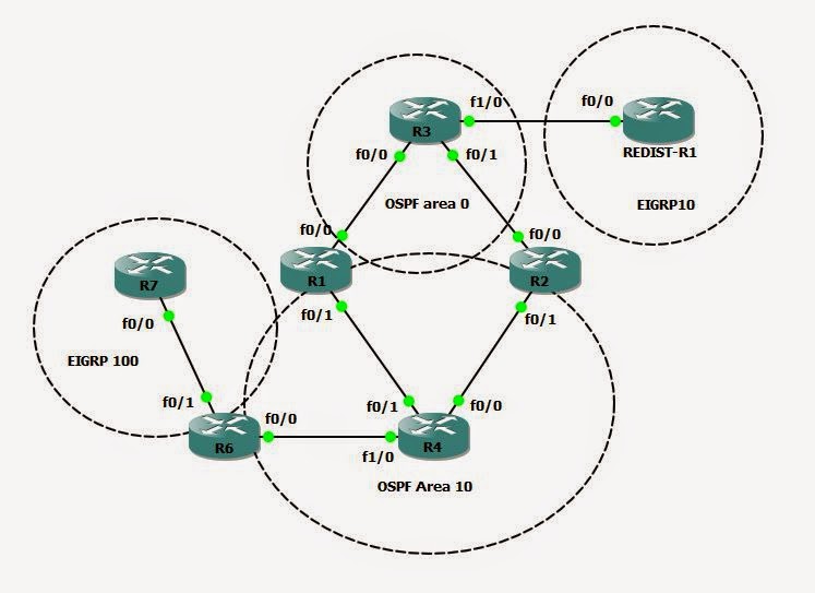
Configuration -
For this – I will configure area 10 as a Stub area, this
means I will need to configure everyone
in the area as a Stub…..
So from this Topology I will need to configure R4, R6, R1
and R2 as Stub routers.
R6(config-router)#area 10 stub
R6(config-router)#
*Mar 1 00:09:03.615:
%OSPF-5-ADJCHG: Process 10, Nbr 4.4.4.4 on FastEthernet0/0 from FULL to DOWN,
Neighbor Down: Adjacency forced to reset
R6(config-router)#
================
R4(config-router)#area 10 stub
R4(config-router)# *Mar
1 00:09:54.287: %OSPF-5-ADJCHG: Process 10, Nbr 2.2.2.2 on
FastEthernet0/0 from FULL to DOWN, Neighbor Down: Adjacency forced to reset
*Mar 1 00:09:54.291:
%OSPF-5-ADJCHG: Process 10, Nbr 1.1.1.1 on FastEthernet0/1 from FULL to DOWN,
Neighbor Down: Adjacency forced to reset
R4(config-router)#
*Mar 1 00:09:57.039:
%OSPF-5-ADJCHG: Process 10, Nbr 6.6.6.6 on FastEthernet1/0 from LOADING to
FULL, Loading Done
R4(config-router)#
================
R2(config-router)#area 10 stub
*Mar 1 00:11:24.051:
%OSPF-5-ADJCHG: Process 10, Nbr 4.4.4.4 on FastEthernet0/1 from LOADING to
FULL, Loading Done
R2(config-router)#
================
R2(config-router)#area 10 stub
R2(config-router)#
*Mar 1 00:11:24.051:
%OSPF-5-ADJCHG: Process 10, Nbr 4.4.4.4 on FastEthernet0/1 from LOADING to
FULL, Loading Done
R2(config-router)#
================
Note: we lose the ADJ because we have to do new flooding of
LSAs.
We can now see that we will still have our O routes and our
O IA routes but we will not have our E1 or E2 routes.
We will now have a default route that the ABR will be generating
to the Stub area:
O*IA 0.0.0.0/0 [110/2] via 10.1.24.2, 00:01:33,
FastEthernet0/0
[110/2]
via 10.1.14.1, 00:01:33, FastEthernet0/1
R4#
This should not change to forwarding path, the only
difference is the now when we show an IP OSPF Database there should no longer
be any TYPE 5 LSAs.
R4#sh ip ospf database
OSPF
Router with ID (4.4.4.4) (Process ID 10)
Router
Link States (Area 10)
Link ID ADV
Router Age Seq# Checksum Link count
1.1.1.1
1.1.1.1 275 0x80000004 0x0010AF 2
2.2.2.2
2.2.2.2 265 0x80000004 0x00CCA3 3
4.4.4.4
4.4.4.4 264 0x80000009 0x0028A2 4
6.6.6.6
6.6.6.6 354 0x80000005 0x0098BD 2
Net
Link States (Area 10)
Link ID ADV
Router Age Seq# Checksum
10.1.14.4
4.4.4.4 270 0x80000003 0x00AA4E
10.1.24.4
4.4.4.4 259 0x80000003 0x006E7C
10.1.46.6
6.6.6.6 354 0x80000001 0x00D7E4
Summary Net Link States (Area 10)
Link ID ADV
Router Age Seq# Checksum
0.0.0.0 1.1.1.1 285 0x80000001 0x0093A6
0.0.0.0 2.2.2.2 269 0x80000001 0x0075C0
1.1.1.0
1.1.1.1 285 0x80000002 0x006DC8
1.1.1.0
2.2.2.2 271 0x80000002 0x0063CC
3.3.3.0
1.1.1.1 287 0x80000002 0x002FFF
3.3.3.0
2.2.2.2 271 0x80000002 0x00111A
30.30.30.0
1.1.1.1 287 0x80000002 0x005F7E
30.30.30.0
2.2.2.2 271 0x80000002 0x004198
172.16.13.0
1.1.1.1 287 0x80000002 0x007CF2
172.16.13.0
2.2.2.2 271 0x80000002 0x006802
192.168.23.0
1.1.1.1 287 0x80000002 0x00EBCB
192.168.23.0
2.2.2.2 271 0x80000002 0x00C3F0
R4#
========================
Also – we should note that we now have the 0.0.0.0 routes generated
by the ABRs. This is the default route that the ABR is advertising,
OSPF Stub –
Totally Stubby Area
-removes External routes (LSA 5)
-Removes ASBR advertisements (LSA 4)
-Removes Inter-area default route (LSA 3)
Stub enabled on all routes in the area
#Area (Area) stub
Totally Stubby enabled in the ABR9s) of the area
# area (area) stub no-summary
========================
This will replace all the E 1 & 2 routes and even the LSA
3 routes and simply generate a default-route into the area.
So on R1 and R2 – we will need to change the stub area config
and add the “no-summary” command.
R1(config)#router ospf 10
R1(config-router)#area 10 stub no-summary
------------------------------------------------------
R2(config-router)#area 10 stub no-summary
Now from the database –
R4#sh ip ospf database
OSPF
Router with ID (4.4.4.4) (Process ID 10)
Router Link States (Area 10)
Link ID ADV
Router Age Seq# Checksum Link count
1.1.1.1
1.1.1.1 1002 0x80000004 0x0010AF 2
2.2.2.2
2.2.2.2 991 0x80000004 0x00CCA3 3
4.4.4.4 4.4.4.4 990 0x80000009 0x0028A2 4
6.6.6.6
6.6.6.6 1081 0x80000005 0x0098BD 2
Net
Link States (Area 10)
Link ID ADV
Router Age Seq# Checksum
10.1.14.4
4.4.4.4 997 0x80000003 0x00AA4E
10.1.24.4
4.4.4.4 986 0x80000003 0x006E7C
10.1.46.6
6.6.6.6 1081 0x80000001 0x00D7E4
Summary Net Link States (Area 10)
Link ID ADV Router Age Seq# Checksum
0.0.0.0
1.1.1.1 73 0x80000002 0x0091A7
0.0.0.0
2.2.2.2 34 0x80000002 0x0073C1
R4#
The size of the DB is reduced and we now have only zero
routes for form the ABRs. The only routes we should have are from routes within
our own area.
The potential issues we could run into with the Stub area or
the Totally stubby area. Is that since we’re filtering out the type 5
externals. It would not be valid to have a stub area that has other external
information being redistributed into it.
Example, is if the stub area had other IGP routes being
learned – EIGRP for example – These would not be allowed to be redistributed
into the area because are 10 will disallow and external routes into the
database.
This is where the Not-so-Stubby Area (NSSA) comes is.
NSSA
-allows NSSA external generation (LSA 7)
-Removes External routes (LSA 5)
- Removes ASBR Advertisements (LSA 4)
All routers must agree on the NSSA
# area (area) NSSA (Will appear in routing table as N1 or N2
routes)
ABR does not originate and default automatically
-Can be configured to generate LSA 7 default
#area (area) nssa default-information-originate
Once again all routers in the area will need to be
configured as NSSA stub routers.
Now if I show the Ip ospf database - should no longer have any type 5 LSAa but I
will have the type 7
R7#sh ip ospf database
OSPF
Router with ID (19.19.19.7) (Process ID 10)
Router
Link States (Area 10)
Link ID ADV
Router Age Seq# Checksum Link count
1.1.1.1
1.1.1.1 1009 0x80000002 0x0014AD 2
2.2.2.2
2.2.2.2 1009 0x80000002 0x00D0A1 3
4.4.4.4
4.4.4.4 238 0x80000006 0x001006 4
6.6.6.6
6.6.6.6 226 0x80000006 0x00F7E8 3
19.19.19.7
19.19.19.7 225 0x80000005 0x00DF1C 1
Net
Link States (Area 10)
Link ID ADV
Router Age Seq# Checksum
10.1.67.7
19.19.19.7 225 0x80000001 0x00D570
Summary Net Link States (Area 10)
Link ID ADV
Router Age Seq# Checksum
0.0.0.0
1.1.1.1 1050 0x80000001 0x0093A6
0.0.0.0
2.2.2.2 1049 0x80000001 0x0075C0
1.1.1.0
1.1.1.1 1045 0x80000001 0x006FC7
1.1.1.0
2.2.2.2 1004 0x80000001 0x0065CB
3.3.3.0
1.1.1.1 1007 0x80000001 0x0031FE
3.3.3.0
2.2.2.2 1006 0x80000001 0x001319
30.30.30.0
1.1.1.1 1007 0x80000001 0x00617D
30.30.30.0
2.2.2.2 1006 0x80000001 0x004397
172.16.13.0
1.1.1.1 1047 0x80000001 0x007EF1
172.16.13.0
2.2.2.2 1006 0x80000001 0x006A01
192.168.23.0
1.1.1.1 1007 0x80000001 0x00EDCA
192.168.23.0
2.2.2.2 1046 0x80000001 0x00C5EF
Type-7 AS External Link States (Area 10)
17.17.17.0
19.19.19.7 334 0x80000001 0x00408D 0
18.18.18.0
19.19.19.7 334 0x80000001 0x001CAE 0
19.19.19.0
19.19.19.7 334 0x80000001 0x00F7CF 0
R7#
Note the ABR now does not originate the default. We can
configure it to – but it will not do this automatically. # area (area) nssa
default-information-originate
R1(config-router)#area 10 nssa default-information-originate
R1(config-router)#^Z
R2(config-router)#area 10 nssa default-information-originate
O*N2 0.0.0.0/0 [110/1] via 10.1.24.2, 00:00:13,
FastEthernet0/0
[110/1]
via 10.1.14.1, 00:00:13, FastEthernet0/1
R4#
---------------------------------------
Note: remember the path selection of OSPF.
Also if we we’re to go to a router insde another are – area
0 – we should se the NS1 or 2 route show as an E1 or 2 route.
R1#sh ip route
Gateway of last resort is not set
17.0.0.0/24 is
subnetted, 1 subnets
O E2 17.17.17.0
[110/20] via 10.1.14.4, 00:06:30, FastEthernet0/1
O E2 18.18.18.0
[110/20] via 10.1.14.4, 00:06:30, FastEthernet0/1
This is because it does not know the other area is a NSSA
area.
Not so totally stubby
area:
Not-so-totally stubby area
-allows NSSA External generation
-Removes External routes (LSA5)
-Removes ASBR advertisements (LSA 4 )
_removes Inter-area default route (LSA3)
NSSA enabled on all routers in area
#area (area )nssa
Totally Stubby enabled on ABR(s) of the are
# area (area nssa no-summary

